


Helico-centrifugal pump
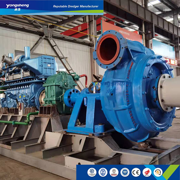
Brand Yongsheng
The hellico-centrifugal pump was developed by a Peruvian research institute in 1960s, it was used to transport fish at that time, later, it was started to be used for conveying solid-liquid binary fluids, it can also be used for drainage and conveying liquids with high viscosity. To prevent clogging by solid matters and ensure their smooth outflow, the open (closed) type impeller has a twisted helical blade, it is on the conical hub body and extends out from the suction inlet along the axial direction, the radius of the blade is gradually increasing to form a helical propulsion effect, the impeller of the scroll portion generates a centrifugal effect as that of a general centrifugal pump. The acute angle part of the impeller pushes the debris to the pace near the axes, and then the debris are pushed further forward by spiral effect. This pump is like a combination of a positive displacement pump and a centrifugal pump, so it is called helicon-centrifugal pump. As this pump has the functions of a displacement pump and a centrifugal pump, so it has the following features compared with general centrifugal pumps:
1. It has good non-clogging, performance, the single (double) blades form a large channel, together with inlet guide function and helical propulsion effect, the pump has good common properties, it can be used to convey liquid containing large particles and fiber materials, and it can be used to convey liquid with a concentration that is much higher than that can be conveyed by other non-clogging pumps (Figure 1, Figure 2).2. It has good non-damage performance. The solid-liquid binary-fluids are gradually propelled forward in this pump without sudden changes in the direction of flow, the flow is smooth, and thus it causes less damage to the conveyed materials compared with other types of non-clog pumps, so it can be used to convey fish, shrimps, and fruits etc.
3. It has high efficiency. Figure 3 is the comparison between the performance of helicon-centrifugal pumps and the performance of ordinary impurity pumps and vortex pumps. From this we can know that the efficiency of helicon-centrifugal pump is 10% to 20% higher than vortex pumps; 5% to 10% higher than ordinary impurity; and its efficiency is nearly the same as that of ordinary clear water centrifugal pumps (about 5% lower ).
4. The power curve is relatively even, the change of the curve along with the flow rate is small, generally there is no overload.
5. It has a steep descent head curve, ordinary centrifugal pump have relatively flat head curves, especially for low specific speed pumps, it is difficult to have steep descent head curves. Figure 3 shows the head-flow rate curves of a variety of specific speed helicon-centrifugal pumps, all of these curves are steep curves. In these curves, the slope of the flow change is small relative head changes, so stable operation can be ensured.
6. The suction performance of this pump is excellent; its blade extends out into the suction inlet, similar to that of axial flow pumps, the pump can still work normally even if there is a local cavitation. Thus, this pump can pump gas-containing liquids, when a small amount of gases is sucked into the pump, the performance, vibration and noise of the pump will not change. When the gas content reaches 40%, it may have severe vibrations repeatedly, but the pump can still work.
7. The pump will have noise and vibrations when flow rate is small, and the pump will have large noise and vibrations when it changes from the flow rate with highest efficiency to the flow rate near the shut off point.
8. It is relatively difficult to manufacture the impeller of the pump as it requires high impeller balance.
The application scope of the helicon-centrifugal pumps is increasing, in addition to conveying solid-liquid binary-phase fluids, it is also used to convey viscous fluid, test results showed that if the Reynolds number is within the range of 3×10³
10, Sensors: This pump uses a submersible motor, it has sensors (for temperature, leakage, bearing temperature) inside, the motor is connected to the sensor, and the motor circuit line is connected to the input end of the dedicated control box (the dedicated control box needs to be provided separately), the output end is connected to the submersible motor control cabinet; for the dedicated control cabinet, model, and manufacturers, see (submersible motor internal sensor functions table).
11. Annexes: 1. Three-phase AC induction asynchronous motor factory test report. 2. Provisions on submersible motor control cable wiring colors. 3. Submersible motor’s internal sensor function table. 4. Pump test report.
|
Model
|
Q
(m3/h)
|
H
(m)
|
N
(r/min)
|
h
(﹪)
|
N shaft
(kW)
|
|
Lx250-200-35
|
500
|
35
|
1450
|
79
|
60.3
|
2. Technical parameters of helico-centrifugal pumps
|
Name
|
Head curve slope
Ho/Hop
|
Highest efficiency(Proportional to ordinary impellers)
|
NPSH
(proportional to ordinary impellers)
|
Features and applications
|
|
Semi-open type
|
1.28
|
0.92
|
1.05
|
The impeller wear gap increases, the pump performance decreases, the non-clogging performance is poor, it cannot convey materials with large particles and long fibers
|
|
Spiral flow type
|
1.14
|
0.68
|
2.5
|
With good non-clogging performance and good wear resistance, suitable for conveying materials with large particles; with poor non-destructive performance, it has large destructive effect to the conveyed materials; it can be sued to convey gas-containing liquids, not suitable for conveying liquids containing long fiber materials.
|
|
Single channel type
|
+++++
|
0.95
|
1.2
|
It has good non-clogging performance and good non-damage performance to conveyed materials, it is suitable for conveying materials with large granules and long fibers; it has good abrasion resistance and has high balance requirement, and has relatively poor smooth running performance
|
|
Double-channel type
|
1.56
|
0.95
|
1.2
|
Its carrying capacity is slightly lower than single-channel type, due to its good balancing performance, it can work stably; it is suitable for places requiring high head and high flow rate pumps
|
|
Helico-centrifugal pump
|
1.7
|
0.95
|
1.0
|
It has good non-clogging performance and good non-damage, suitable for conveying liquids containing large granules and long fibers; it has little damage to conveyed materials, i.e., it has good non-damage performance, and has relatively high balance requirement
|

Helico-centrifugal pup
Ordinary impurity pump
Vortex pump
Fig.3. Performance curve diagram
IV. Installation and operation methods, operation precautions and maintenance of the pump
1. Pump installation and operation methods
1. Before installation the use, the user should carefully check whether the appearance of the electric pump is in good condition, check each connection to see whether there is any loose or leakage, and whether the electric cable is damaged or cracked. And carefully check flow rate, head, power etc on the nameplate, in order to ensure correct use.
2. Use a megameter to measure the electric pump’s cold insulation resistance, which should be greater than 50 megohms, if it is lower than this value, the excessive moisture should be removed before it is used again;
3. The pump should have a separate power switch, and should be reliably grounded,
4. If the cable of the electric pump is not long enough, the extended cable must have a larger diameter which should be two times of that of the original cable, and the extended cable should be firmly connected and the number of connectors should be minimized and cable connector, and no connector should be submerged in water;
5. Check whether the pump can normally start and run (empty running should not exceed two seconds), whether the rotating direction is correct (the running direction is indicated on the pump cover), if the rotating direction of the three-phase electric pump is incorrect, you can correct it by changing any two main lines;
6. Tie a rope on the handle or hoist ring of the pump in order to place it, it is strictly prohibited to use electric cable of the pump to hang, place, lift or pull the pump.
2. Precautions in use of the pump
1. When the pump works, pay close attention to the water level, never allow the pump be above water surface or run without water;
2. When the pump works, do not touch and move it to prevent accidents;
3. Whenever the electric pump is used, an over current protection switch should be installed to protect the electric pump and cut off the power if there is any exceptional circumstance, so as to ensure that motor windings will not burn out;
4. All kinds of electric pumps should be well grounded whenever they are used, the yellow-green colored wire should be sued as ground wire and ground symbol should be used according to the requirements of the new standard; if necessary, use a multimeter to measure the ground wire in order to prevent wrong wiring which may cause accidents, if the pump can not be grounded, a leakage protector should be used;
5.Do not use the pump if the three-phase voltage is not stable or if there is an open phase, so as not to burn the windings;
6. In case of electric pump failure, no one, except professional repairers, is allowed to disassemble the pump, after disassembly, the electric pump must be check for air tightness, it can be used again only after the test result shows that it conforms to the requirements.
7. The electric pump is strictly prohibited to run without water
8. The cable connector should not be emerged in water, if the cable ruptures or scratched, it should not be used so as to prevent water from infiltrate into the cavity of the electric pump.
Note: The used head shall not be less than 0.7 time of the rated head.
3 Care and Maintenance
1. Regularly check the cold insulation resistance between winding and cabinet of the electric pump, which should not be less than 50 megohms, if it is lower than this value, it should be solved, or disassemble the electric pump to dry the stator, the pump can be used again only after the insulation resistance becomes normal;
2. After each use (especially after pumping viscous slurry), the pump should be placed in running water for a few minutes to clear off the dirt inside and outside of the pump, and wipe off the moisture, then store the pump in a dry and well-ventilated place, the pump should be emerged in water it is no used for a long time, when the temperature is too low, take the pump out from water in order to prevent electric pump casing from frost cracking;
3. Check the cable, carefully examine the cable surface to see whether it is scratched or broken, or has any small holes and other defects, otherwise, the cable should be replaced immediately;
4. After the electric pump is disassembled and repaired, its sealing performance must reach 0.2Mpa, there should be no leakage during the pressure test lasting for 3min;
5. After the electric pump works for 1000 successive or accumulated hours, check the fasteners and sealing parts, if there is any oil leakage, timely replace the related parts, No. 10 machine oil should be used in oil chamber;
6. The machine oil of the electric pump should be replace once every 1500 accumulated working hours (the oil chamber is in the water inlet joint), unscrew the oil plug screw, add 10 # methane oil up to 80% of the capacity of the oil chamber;
7. The wearing parts (such as rolling bearings, overall oil seals) of the electric pump should be replaced once every 3000 accumulated working hours, in order to prevent greater losses caused by seal damage;
8. If the pump is not used for a long time, it should be washed clean, if the surface coating falls off, it should be painted again, after repainting, store it a cool, dry and well ventilated place for safekeeping.
Note: To prevent electric shock, make sure to cut off the power before repairing or cleaning the electric pump.
|
Motor model
|
Yz280A-4/90kw
|
|
|
|
|
|
|
|
Date
|
2011-3-28
|
|||
|
Motor model
|
R1
Ω
|
R2
Ω
|
R3
Ω
|
Insulation resistance mΩ
|
Inter-turn status
|
Withstand voltage
1.76kv
|
Locked-rotor voltage
V
|
Ikx
A
|
Locked-rotor power
W
|
Open-circuit voltage V
|
Iox
A
|
No-load power W
|
Test result
|
|
|
0.039
|
0.039
|
0.038
|
500
|
Qualified
|
Qualified
|
100
|
200
|
12500
|
380
|
43.2
|
16003
|
Qualified
|
Rules of submersible motor control cable wiring colors:
Red ------ lower float ball
Black------ upper float ball
White ------bearing temperature measurement
Blue ------ stator temperature measurement
Yellow ------ oil and water control head
Yellow ------ ground wire (ground yellow wire with a knot)
|
Control cable color
|
Two blue wires
|
Two black wires
|
Two red wires
|
One yellow wire
|
Two white wires
|
One yellow wire
|
|
Sensor name
|
Winding temperature measurement element
|
Leakage float switch inside the wiring box
|
Leakage float switch inside the motor
|
Leakage electrode inside the oil chamber
|
Bearing temperature measurement element
|
Ground
|
|
Normal state resistance value
|
0
|
Disconnect
|
Disconnect
|
≥33k%Ω
|
0
|
|
|
Function
|
≥4kΩAfter the stator coil over-temperature protection device actuates when the temperature exceeds 135℃
|
When junction box electric leakage occurs, the float switch state transition resistance R≈0
|
When motor cavity electric leakage occurs, the float switch state transition resistance R≈0
|
When water content of the oil reaches 10%, the electric resistance of the oil and water mixture <33kΩ
|
When bearing temperature exceeds 95℃, R≈∞
|
|
|
Serial No
|
Test Item
|
Measured value
|
Specified value
|
Tolerance value
|
|
1
|
Motor full load current A
|
132
|
180.4
|
|
|
2
|
Motor full load efficiency %
|
93.5
|
91
|
-2.85
|
|
3
|
Motor full load power factor
|
0.8611
|
0.83
|
-0.0283
|
|
4
|
Motor full load slip ratio %
|
4.733
|
|
|
|
5
|
Stator coil temperature rise K
|
10.54
|
≤45
|
|
|
6
|
Motor starting current A
|
450
|
|
|
|
7
|
Starting current / rated current
|
|
|
|
|
8
|
Electric starter torque N.m
|
|
|
|
|
9
|
Starting torque / rated torque
|
|
|
|
|
10
|
Maximum torque of the motor N.m
|
|
|
|
|
11
|
11 Max torque / rated torque
|
|
|
|
|
12
|
Minimum torque N.m
|
|
|
|
|
13
|
Minimum torque / rated torque
|
|
|
|
|
14
|
Withstanding voltage test V
|
1760
|
1760
|
|
|
15
|
Cold insulation resistance MΩ
|
500
|
150
|
|
|
16
|
Stator phase resistance Ω
|
0.038
|
|
|
|
17
|
Motor no-load current A
|
43.2
|
|
|
|
18
|
No-load input power W
|
16003
|
|
|
|
19
|
Iron loss W
|
600.52
|
|
|
|
20
|
Mechanical loss W
|
550.93
|
|
|
|
21
|
Stator full load I2R loss W
|
1221.5
|
|
|
|
22
|
Rotor full load I2R loss W
|
787.8
|
|
|
|
23
|
Stray depletion W
|
400
|
|
|
|
24
|
Total depletion W
|
3560.75
|
|
|
|
25
|
Measured flow rate m3/h
|
498
|
500
|
±4.00
|
|
26
|
Measured lift m
|
34.87
|
35
|
±3.25
|
|
27
|
Measured pump efficiency %
|
78.126
|
79
|
-4.5
|
|
Remarks
|
|
|||
1.Why YS is your Best Trustworthy Dredger Manufacturer?
Add:300m West of Huanglou Government, Qingzhou City, Shandong Province, China
Tel:+86 15864229511
Whatsapp/Wechat:+86 15864229511 Hailey@YongShengShipBuilding.com